


LINE / ANTENNA SWITCHERS
Former switching panel with the RPA-
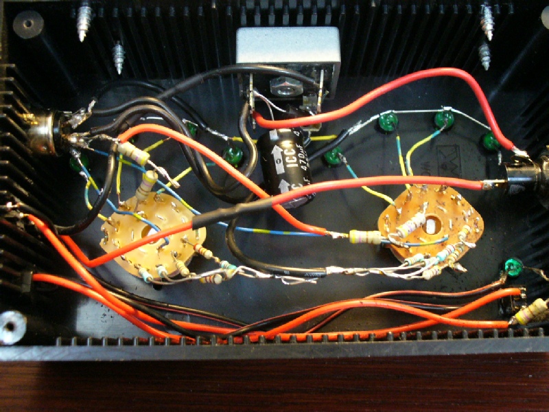
This is version number two. The first having been destroyed during the lightning strike event after just one month of use. The whole circuit was based on this design . It wasn't necessary to use band pass filters as shown. I made two identical four inputs units on the same board in order to feed the two feedlines inputs of the USB switcher. This allow me to use various wire antenna combinations. With quad NAND gates, I’ve added two more "default" relays. The unit is always powered but I can leave the two most used antennas without switching any relays. I found very clever the use of the LM3914 comparator because with only four wires, it control the dual switcher perfectly.
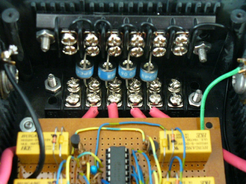
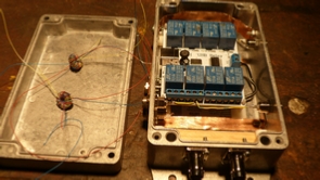
I've also added static discharge protection using gas discharge tubes. I had for over thirty years some high voltage wire (in red) that I’m using here, hopefully to prevent high voltage from jumping to the board. At least, this is what I hope! I preferred to use screws instead of soldering to make sure that the contact to ground would last longer under higher peaks.
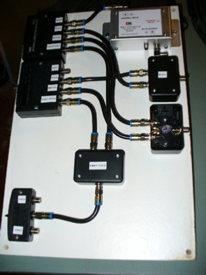
A general view of the unit. All external screws are made from stainless steel. During the Summer, I don't use it because of the thunderstorms. Ii is simply removed it and kept inside. The Summer setup consist in two Beverages connected to the two main feedlines and that’s about it.
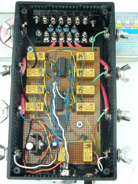
Inside view of the remote switcher indoor controller with its array (or bunch!!) of resistors.
I’m pleased to share here my USB coax lines controller. It has been designed to replace the aging manual coax switcher I've been using for years (shown on top) . Even after replacing the A-
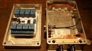
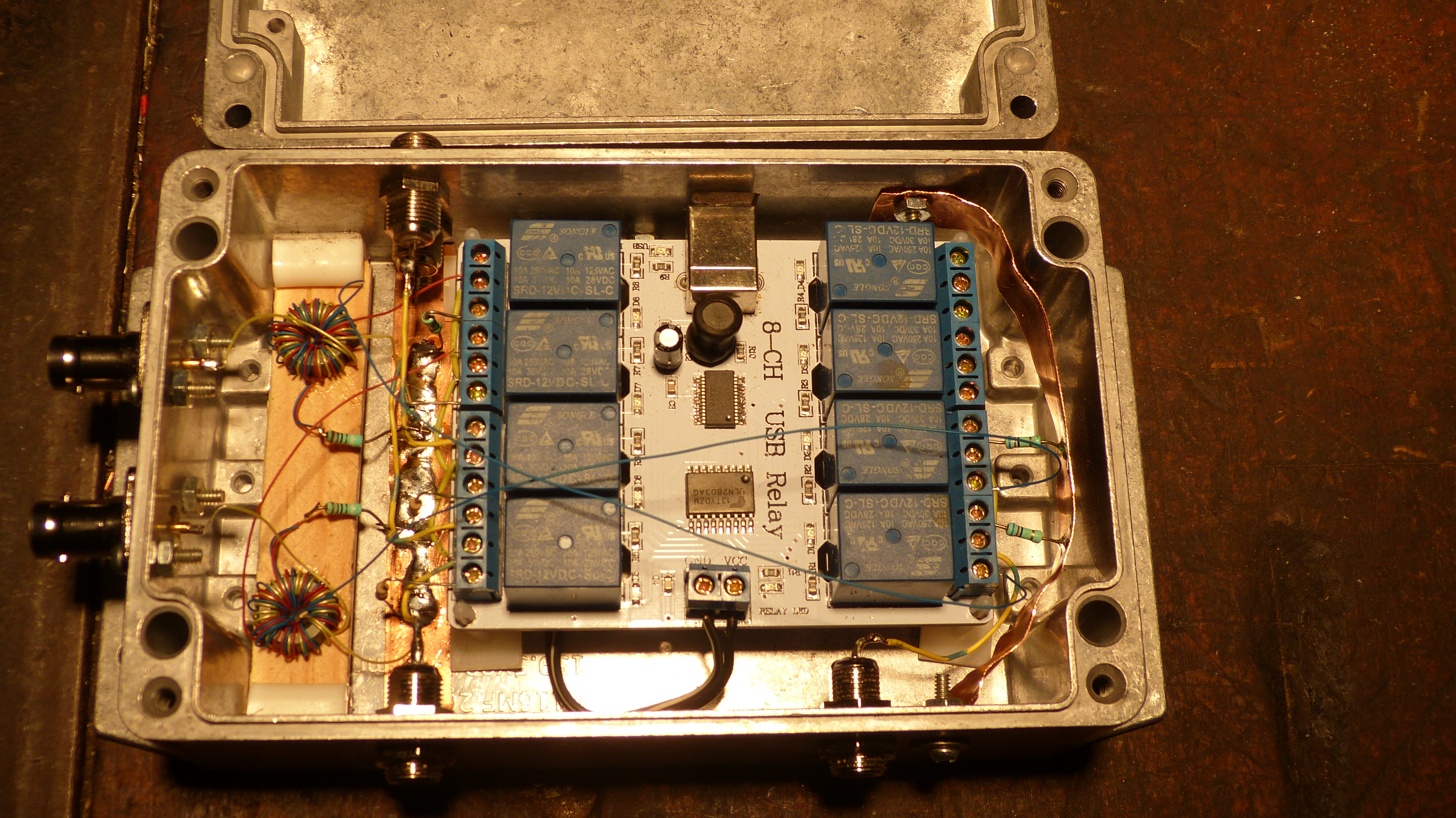
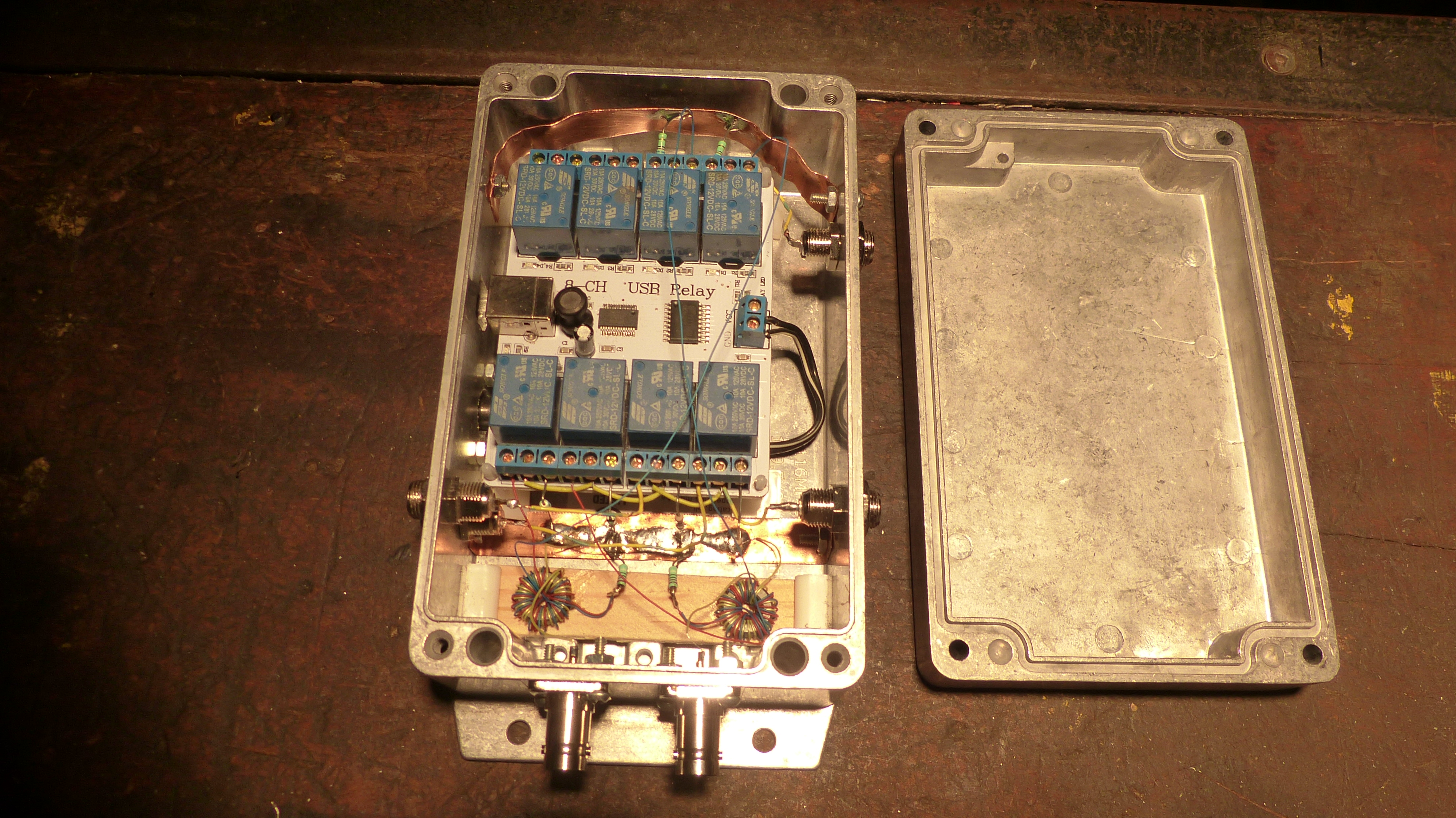
The switcher was made by using an eight channels USB relay board used for home automation, which I simply adapted for my needs. With that setup, it can commute up to four coax lines towards two outputs in order to feed both phaser inputs.
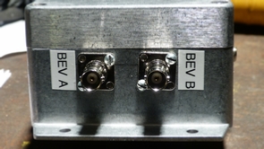
Two of those four lines (the choked one) are used to route the signal from three Beverage antennas and two long wires which can be selected via a separate remote wire antenna switcher (bottom page) mounted right at feedpoint that I have been using successfully for years. The switcher also includes two homebrew splitters described here that divides the two main coax lines. When the relays are at "rest" position, each coax lines get grounded via a 62 ohms resistor (a value not so critical having enough of those on hand).
The two pictures opposite gives a general view of the complete switcher assembly. As shown, both splitters are glued to a wooden piece in order to keep them isolated from any metal object. For grounding, I used copper foil that I’ve bolted to the chassis. This is where most ground connections are ending.
By doing this, it certainly help not getting unwanted noise induced by ground loops for instance. I’ve also kept the chassis ground isolated from the USB/laptop ground again to keep the unwanted noise away.
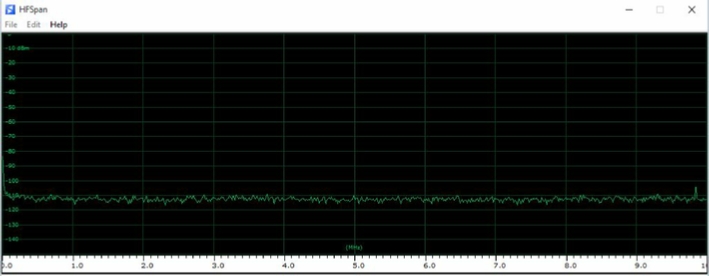
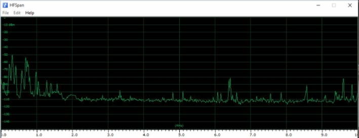
With this new setup and this, combined with a "tightening operation" of all the in-
Of the two above 0-
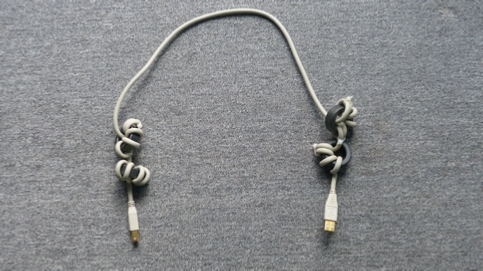
For good measure, I’ve also added some ferrites to my USB cable in order to minimize induced laptop noise. The toroids are FT140-

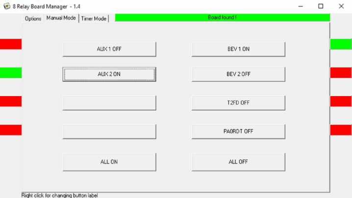
Above, the ugly look of the native software and unfortunately, as I’m no programmer, I’ll have to live with it. I would have preferred a much smaller window and I also would have liked to have it controlled throughout the Internet, just to name a few major improvement here …

ANALOG CATV FEEDLINE SWITCHER
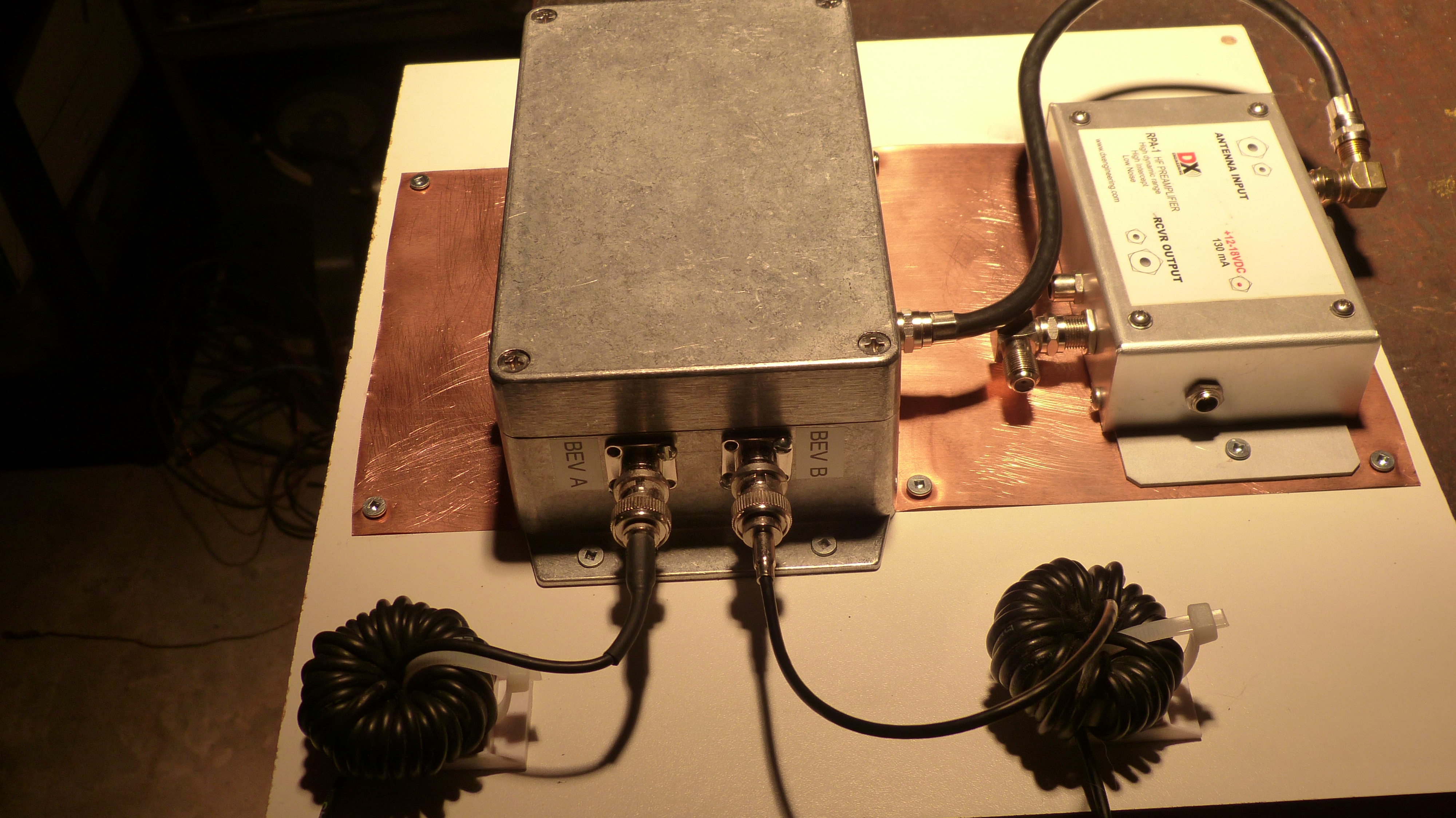
A view at the switching box next to the DX Engineering RPA-
The copper sheet is connected to the the shack ground plane (more on the Lightning Protection page)
COMPUTER CONTROLLED USB FEEDLINE SWITCHER
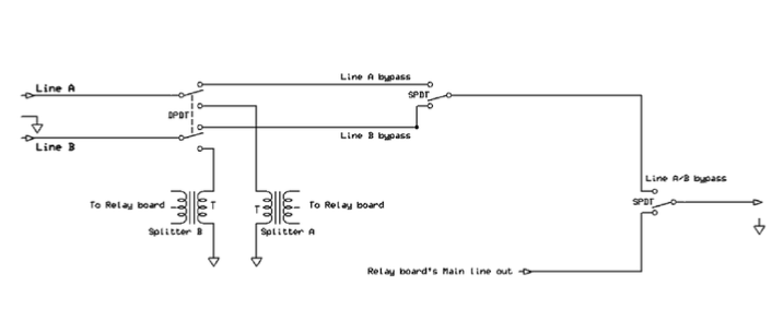
Above is a system of bypass switches that I’ve added later to the relay box allowing me to switch manually between one of the two main coax lines in case of a circuit board or computer failure. There’s no phasing possible when using this configuration though.
| Receiving Station Setup |
| Receivers |
| Antennas |
| Line / Antenna switchers |
| Lightning protection |
| Others |
| Conventional receivers |
| Microtelecom Perseus |
| SDRPlay |
| Beverages |
| K9AY |
| PA0RDT Mini-Whip |
| Miscellaneous |
| Asian audio files |
| African audio files |
| European audio files |
| Middle-East audio files |
| Latin American-Caribbean audio files |
| 2015 St-Patrick' solar storm audio files |
| DX Curiosities |
| August 2007 bandscan |
| August 2014 bandscan |
| FMDX equipments |
| FM logs 2017-2018 |
| FM logs 2020 |
| FM logs 2021 |
| FM logs 2022 |
| FM logs 2023 |
| FM logs 2025 |